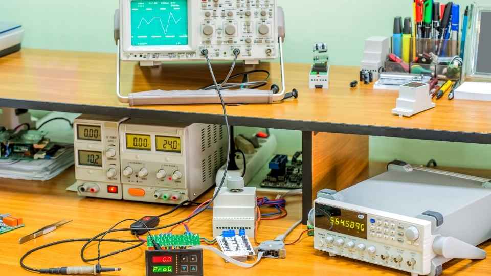
In today's rapidly advancing technological landscape, the seamless integration of sensors and actuators with microcontrollers has become paramount in various industries.
Imagine a scenario where an automated greenhouse system efficiently adjusts temperature and humidity levels based on real-time data from sensors, ensuring optimal plant growth.
This article delves into the intricacies of microcontroller interfacing, providing a comprehensive guide on connecting the dots between sensors and actuators.
From understanding communication protocols to troubleshooting potential issues, this piece aims to equip professionals with the knowledge needed to navigate the complexities of microcontroller interfacing successfully.
Key Takeaways
- Microcontrollers serve as the brain of electronic systems.
- Proper wiring techniques ensure reliable communication.
- Actuator selection depends on force, speed, precision, size, and environment.
- Communication protocols should be chosen based on data transfer speed, range, and power consumption.
Understanding Microcontroller Interfacing Basics
To understand microcontroller interfacing basics, one must grasp the fundamental principles of connecting sensors and actuators to effectively control and monitor external devices.
Microcontrollers, such as Arduino or Raspberry Pi, serve as the brain of electronic systems by processing input signals from sensors and generating output signals for actuators.
The first step in microcontroller interfacing is selecting appropriate sensors and actuators based on the desired functionality. Sensors can include temperature, light, pressure, or motion detectors while actuators may consist of motors, relays, or LEDs.

Once selected, these devices need to be connected to the microcontroller using various interface protocols like I2C or SPI. Proper wiring techniques ensure reliable communication between the microcontroller and peripherals.
Additionally, software programming is required to configure the microcontroller's pins for input/output operations and implement specific functionality through code execution.
Understanding these basic principles enables freedom in designing custom applications that interact seamlessly with external devices through microcontrollers' versatile interfaces.
Exploring Different Types of Sensors and Actuators
Exploring different types of sensors and actuators is essential in understanding the capabilities and limitations of these components.
Sensors can range from simple temperature sensors to more complex ones like accelerometers or gas sensors, each serving a specific purpose in measuring physical quantities.
Actuators, on the other hand, are devices that can convert electrical signals into mechanical motion or perform actions such as opening and closing valves or switching on lights.
Sensor Types Explained Briefly
There are various types of sensors used in microcontroller interfacing, each serving a specific purpose. In order to effectively connect the dots between microcontrollers and sensors, it is important to understand the different types available.

One common type is the temperature sensor, which measures ambient temperature and provides valuable input for applications such as climate control systems.
Another type is the proximity sensor, which detects the presence or absence of objects within a certain range. This can be useful in robotics or security systems where object detection is crucial.
Additionally, there are light sensors that measure light intensity and enable automatic adjustments in lighting systems.
Other sensor types include pressure sensors, humidity sensors, motion sensors, and many more.
Understanding these different sensor types allows for precise integration with microcontrollers to achieve desired outcomes in various applications.
Actuator Options and Uses
Actuators play a vital role in converting electrical signals into physical movement, enabling precise control and manipulation in various applications. They are essential components in systems that require mechanical motion or force generation. Here are three types of actuators commonly used:
Electric Actuators: These actuators use electric power to create linear or rotational motion. They are reliable, efficient, and provide accurate positioning.

Pneumatic Actuators: By utilizing compressed air or gas, pneumatic actuators generate linear or rotary motion. They offer high-speed operation and can generate large forces.
Hydraulic Actuators: These actuators use hydraulic fluid to produce linear or rotary motion. They provide high-force capabilities and smooth operation.
Choosing the right actuator depends on factors such as required force, speed, precision, size constraints, and environmental conditions. Understanding these considerations is crucial for selecting the optimal component for your application.
Now let's explore how to choose the right component for your specific needs.
Choosing the Right Component
To select the most suitable actuator for your specific requirements, it is essential to carefully consider factors such as force, speed, precision, size constraints, and environmental conditions.
When choosing an actuator, you must first determine the amount of force required to move or manipulate the object. This will help you select an actuator with sufficient torque or linear force capability.
The speed at which the actuator needs to operate is another crucial factor. If high-speed movement is necessary, a motor-based actuator may be preferred over a hydraulic or pneumatic one.
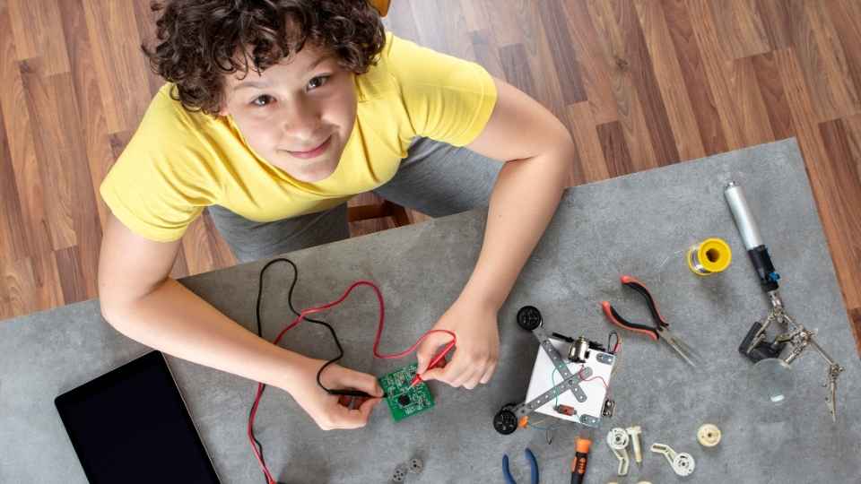
Precision refers to the accuracy and repeatability of the actuator's movements.
Size constraints should also be taken into account to ensure that the actuator fits within the available space.
Finally, environmental conditions such as temperature range and humidity levels should be considered to select an actuator that can withstand these conditions without compromising performance or reliability.
Choosing the Right Communication Protocol for Your Project
When selecting the most suitable communication protocol for a project, it is crucial to consider factors such as data transfer speed, range, and power consumption. Each project has unique requirements that need to be met in order to achieve optimal performance and efficiency.
Here are three key considerations when choosing a communication protocol:
Data Transfer Speed:
Evaluate the amount of data that needs to be transferred and the desired rate of transmission.
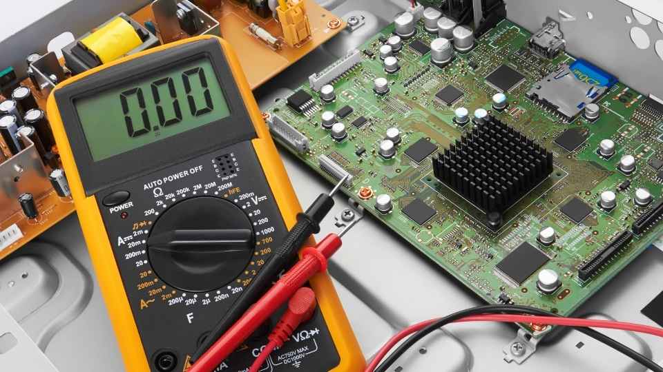
Consider protocols like USB or Ethernet for high-speed data transfer.
For low-power applications, opt for protocols with lower data rates like I2C or SPI.
Range:
Determine the distance over which your devices need to communicate.
Bluetooth or Zigbee can be used for short-range communications within a few meters.
Cellular networks or Wi-Fi are suitable for long-range communications over larger areas.
Power Consumption:
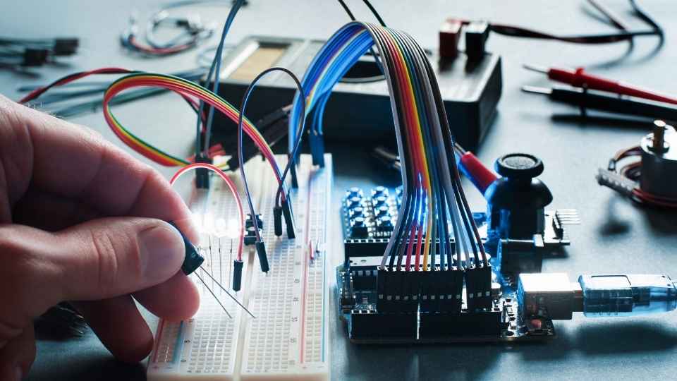
Assess the power requirements of your project and select a protocol accordingly.
Low-power protocols like LoRaWAN or Zigbee can extend battery life in wireless applications.
Ethernet or Wi-Fi may require more power but offer higher data transfer rates.
Considering these factors will help you choose the right communication protocol for your project, ensuring efficient data transfer while minimizing power consumption and meeting specific range requirements.
Connecting Sensors to Microcontrollers: Wiring and Pin Configuration
One important aspect of connecting sensors to a microcontroller involves understanding the wiring and pin configuration, which ensures proper communication and data acquisition between the two components.
The first step is to identify the type of sensor being used and its corresponding pinout diagram. This diagram provides information on which pins are responsible for power supply, ground connection, and data transmission. It is crucial to follow this pinout diagram precisely during the wiring process to prevent any issues or malfunctions.
Next, it is essential to choose the appropriate wires with suitable lengths for connecting the sensor pins to the microcontroller's input/output (I/O) pins. The choice of wire gauge should be based on factors such as signal integrity, power requirements, and distance between the sensor and microcontroller.
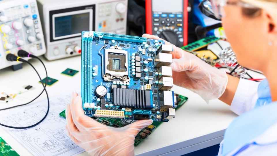
Once all connections are made, it is necessary to configure the microcontroller's I/O pins accordingly. This involves setting up correct voltage levels, enabling pull-up or pull-down resistors if needed, and configuring any necessary interrupt settings.
Interfacing Actuators With Microcontrollers: Controlling Outputs
Controlling outputs on a microcontroller involves configuring the appropriate I/O pins and ensuring the proper voltage levels, enabling necessary resistors, and setting up any required interrupt settings. To effectively interface actuators with microcontrollers, it is crucial to follow these steps:
- Identify the specific actuator you wish to control, such as motors or LEDs.
- Determine the voltage and current requirements of the actuator.
- Connect the actuator to an appropriate output pin on the microcontroller board.
- Ensure a suitable power supply is connected to provide sufficient power for the actuator.
- Use transistors or driver circuits if necessary to handle higher currents or voltages.
- Write code in your preferred programming language that will generate signals through the configured pins to control the actuator.
Mastering SPI, I2C, and UART Communication Protocols
Mastering SPI, I2C, and UART communication protocols is essential for successful microcontroller interfacing.
These protocols allow for efficient and reliable data transfer between the microcontroller and various peripherals.
Understanding how to choose the right protocol based on application requirements and troubleshooting common communication issues ensures smooth operation of the system.
Choosing the Right Protocol
When selecting a protocol, it is crucial to consider factors such as data transfer speed, power consumption, and compatibility with the microcontroller and peripherals. These considerations will ensure optimal performance and seamless communication between the microcontroller and sensors/actuators. Here are three key factors to consider when choosing the right protocol:
- Data Transfer Speed:
- Evaluate the required data rate for your application.
- Consider the maximum speed supported by each protocol.
- Choose a protocol that can handle your desired data transfer rate.
- Power Consumption:
- Assess energy requirements of your system.
- Look for protocols that offer low-power modes or sleep features.
- Opt for a protocol that minimizes power consumption during idle periods.
- Compatibility:
- Check if the microcontroller supports the chosen protocol.
- Ensure compatibility with sensors and actuators you plan to use.
- Verify if any additional hardware or software is needed for implementation.
Considering these factors will help you make an informed decision when choosing a communication protocol for your microcontroller interfacing needs. Now, let's explore troubleshooting techniques for communication issues with these protocols.
Troubleshooting Communication Issues
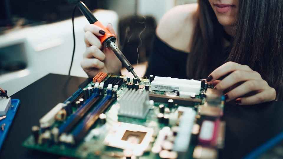
To resolve communication issues with different protocols, it is important to identify and address potential problems. These problems include incorrect wiring, incompatible baud rates, or software configuration errors.
Incorrect wiring can lead to signal loss or improper connections between the microcontroller and the sensor/actuator. Incompatible baud rates can result in data transmission errors and unreliable communication. Software configuration errors may occur when the settings for data format, parity, or stop bits are not properly configured.
To troubleshoot these issues, one should start by checking the wiring connections and ensuring they match the specified pinouts. Next, verify that the baud rate settings on both devices are compatible. Finally, review the software configurations to ensure they align with the requirements of both devices.
Proper troubleshooting and debugging of interfacing issues will help establish seamless communication between microcontrollers and sensors/actuators.
Next Section: Troubleshooting and Debugging Interfacing Issues
Troubleshooting and Debugging Interfacing Issues
One effective approach to resolving interfacing issues in microcontroller systems involves meticulous troubleshooting and diligent debugging techniques. When faced with interface problems, it is crucial to follow a systematic process to identify and rectify the underlying issues. Here are three key steps that can help you troubleshoot and debug interfacing problems effectively:
- Check hardware connections:
- Ensure all connections between the microcontroller, sensors, and actuators are secure.
- Verify that the correct pins are being used for communication.
- Inspect for any loose wires or damaged components.
- Review software configuration:
- Double-check if the correct libraries or drivers are being used.
- Verify that the code is correctly configured for the specific sensor or actuator.
- Check for any conflicting settings or incorrect parameter values.
- Debug with logging and testing:
- Utilize debug logs to track program flow and identify potential errors.
- Use test equipment, such as logic analyzers or oscilloscopes, to monitor signals and validate their integrity.
- Implement test cases to isolate problematic areas of code and verify expected behavior.
Frequently Asked Questions
What Are the Advantages and Disadvantages of Using SPI, I2C, and UART Communication Protocols for Microcontroller Interfacing?
Advantages and disadvantages of SPI, I2C, and UART communication protocols for microcontroller interfacing include factors such as data transfer speed, complexity, number of devices supported, power consumption, and noise immunity. Each protocol has its own trade-offs.

How Can I Determine the Appropriate Voltage Levels for Connecting Sensors and Actuators to Microcontrollers?
Determining appropriate voltage levels for connecting sensors and actuators to microcontrollers involves understanding the specifications of the components being used, such as their operating voltage range and input/output characteristics. This ensures compatibility and optimal performance in the system.
Are There Any Specific Considerations or Precautions to Take When Connecting Multiple Sensors or Actuators to a Single Microcontroller?
When connecting multiple sensors or actuators to a single microcontroller, several considerations and precautions should be taken. These include ensuring sufficient power supply, addressing potential signal interference, managing data communication protocols, and implementing appropriate voltage level shifting techniques.
Can I Use Wireless Communication Protocols, Such as Bluetooth or Wi-Fi, for Microcontroller Interfacing?
Yes, wireless communication protocols such as Bluetooth or Wi-Fi can be used for microcontroller interfacing. These protocols provide a convenient and efficient way to connect sensors and actuators to a microcontroller without the need for physical connections.
How Can I Troubleshoot and Debug Common Issues That May Arise During the Process of Microcontroller Interfacing?
To troubleshoot and debug common issues in microcontroller interfacing, one should employ a systematic approach that involves thorough testing, analyzing error codes, inspecting connections, and consulting documentation. Applying these techniques can help identify and resolve problems efficiently.
 Basic Electronics ConceptsEssential ToolsCircuit Design BasicsMicrocontrollersDIY Electronics ProjectsRoboticsPrivacy PolicyTerms And Conditions
