
In the world of electronic circuits, calculations can often feel like an enigma waiting to be unraveled. But fear not, for this comprehensive guide aims to demystify those perplexing equations and provide you with a practical understanding of basic electronic calculations.
From Ohm's Law exercises to resistor calculations, capacitor timings to voltage dividers, this article will equip you with the knowledge and skills needed to navigate the intricacies of current flow analysis.
So join us on this enlightening journey as we delve into the fascinating realm of electronic calculations.
Key Takeaways
- Ohm's Law formula (V = IR) is a practical tool for calculating voltage, current, and resistance in electrical circuits.
- Capacitors play a crucial role in storing and releasing electrical energy, and can be used for creating delays, smoothing power supply voltages, and precise timing intervals.
- Understanding voltage division and resistor calculations allows for precise control over voltages in a circuit, enabling customization and protection of components.
- Analyzing current flow is essential for troubleshooting electronic circuits, and considerations such as voltage and impedance are important in audio system design and power supply regulation.
Ohm's Law Exercises
In order to reinforce understanding and application of Ohm's Law, the following exercises will provide practical opportunities for calculating voltage, current, and resistance in various electrical circuits. These exercises are designed to enhance comprehension and proficiency in electronic calculations. By engaging in these activities, individuals can develop a deeper understanding of the relationship between voltage, current, and resistance in electrical circuits.
The exercises will require participants to apply Ohm's Law formula (V = IR) to solve for different variables. Participants will be presented with circuit diagrams where they need to calculate unknown values such as voltage drop across a resistor or the current flowing through a circuit. The exercises will cover a range of scenarios including series and parallel circuits.
These practical exercises aim to empower individuals with the necessary skills to confidently analyze and troubleshoot electrical circuits. By mastering Ohm's Law calculations, individuals can gain freedom and independence in tackling diverse electronic challenges they may encounter.
Resistor Calculations
To accurately determine the resistance value needed in a circuit, it is essential to understand resistor calculations and how they impact the flow of electrical current. Resistor calculations involve using Ohm's Law to calculate the relationship between voltage, current, and resistance in a circuit. Here are two key points to consider when performing resistor calculations:
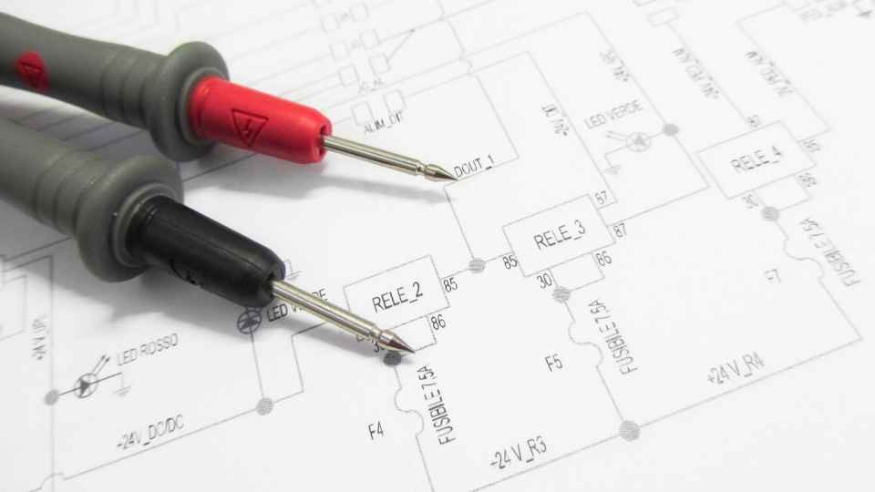
Ohm's Law: This fundamental principle states that the current flowing through a conductor between two points is directly proportional to the voltage across the two points and inversely proportional to the resistance. The formula for Ohm's Law is I = V/R, where I represents current in Amperes (A), V represents voltage in Volts (V), and R represents resistance in Ohms (Ω).
Series and Parallel Resistors: In a series circuit, resistors are connected end-to-end, resulting in a total resistance equal to the sum of individual resistances. In contrast, parallel resistors have their terminals connected together at both ends, resulting in an equivalent resistance that can be calculated using reciprocal values.
Understanding these concepts will empower individuals seeking freedom by enabling them to design and analyze electronic circuits with precision and ease.
Capacitor Timings
Capacitor timings play a crucial role in electronic circuits, as they determine the duration and timing of electrical signals within a system.
A capacitor is an electronic component that stores and releases electrical energy. When a voltage is applied across its terminals, the capacitor charges up, storing energy. The time it takes for the capacitor to charge or discharge is determined by its capacitance value and the resistance in the circuit.
Capacitors can be used to create delays or timing circuits by controlling how quickly they charge and discharge. In digital systems, capacitors are often used to smooth out power supply voltages or to create precise timing intervals.
Understanding Voltage Dividers
Understanding voltage dividers is crucial in electronic circuit design. It allows for the precise distribution of voltage across multiple components. The voltage division principle states that the output voltage across a resistor in a series circuit is proportional to its resistance value compared to the total resistance of the circuit.

Voltage Division Principle
The voltage division principle is a fundamental concept in electronics that allows for the calculation of voltages across multiple resistors in a series circuit. This principle is based on Ohm's Law and is widely used in various electronic applications.
Here are some key points to understand about the voltage division principle:
- The voltage across each resistor in a series circuit is proportional to its resistance value.
- The total voltage across the series circuit can be calculated by summing up the individual voltages across each resistor.
- The ratio of the resistance values determines how the voltage is divided among them.
- Resistors with higher resistance values will have a greater voltage drop across them.
- Resistors with lower resistance values will have a smaller voltage drop across them.
Understanding the voltage division principle is essential for designing and analyzing circuits, as it allows engineers to determine how voltages are distributed within a circuit and make informed decisions regarding component selection and performance optimization.
Calculation of Output Voltage
To calculate the output voltage of a circuit, one must consider the resistors in series and use the voltage division principle to determine how the voltage is distributed across each resistor.
The voltage division principle states that the voltage across each resistor in a series circuit is proportional to its resistance. By applying this principle, one can determine the output voltage by dividing it proportionally across the resistors based on their individual values.
This calculation is crucial in designing electronic circuits as it allows engineers to control and manipulate voltages according to their specific requirements.
Furthermore, understanding how to calculate output voltages enables individuals to troubleshoot circuit malfunctions and optimize performance.

Therefore, mastering this fundamental calculation empowers electronic enthusiasts with greater freedom and control over their projects.
Application in Circuit Design
Applying the principles of voltage division and resistor calculations in circuit design allows engineers to precisely control the distribution of voltage across different components, enabling them to create circuits that meet specific requirements. This level of control is essential for designing electronic devices that operate efficiently and reliably.
Here are some key reasons why these calculations are crucial in circuit design:
Voltage division: By using a combination of resistors, engineers can divide the input voltage into desired proportions. This allows for precise control over the voltages applied to different parts of the circuit.
Component protection: Calculating resistor values ensures that components receive only the appropriate amount of voltage, preventing damage due to excessive current flow.
Customization: Voltage division and resistor calculations enable engineers to tailor circuits according to specific needs, allowing for flexibility and customization in electronic designs.
Current Flow Analysis
Current flow analysis is a crucial aspect of understanding and troubleshooting electronic circuits. It involves analyzing the direction and magnitude of current within a circuit to determine its behavior and performance.
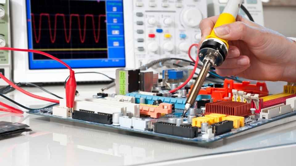
Analyzing Current Flow
Examining the rate of electron movement within a circuit is essential when analyzing current flow. By understanding how electrons move through a circuit, engineers and technicians can design and troubleshoot electrical systems more effectively.
When it comes to analyzing current flow, there are several key considerations:
Voltage: The driving force that pushes electrons through a circuit.
Measured in volts (V).
Determines the intensity of current flow.
Resistance: A property of materials that opposes the flow of electrons.
Measured in ohms (Ω).

Determines how easily or difficultly current can pass through a component.
Understanding these factors allows individuals to calculate and predict current flow within a circuit accurately. This knowledge empowers them to make informed decisions and ensure the efficient functioning of electronic devices.
Current Flow Measurement
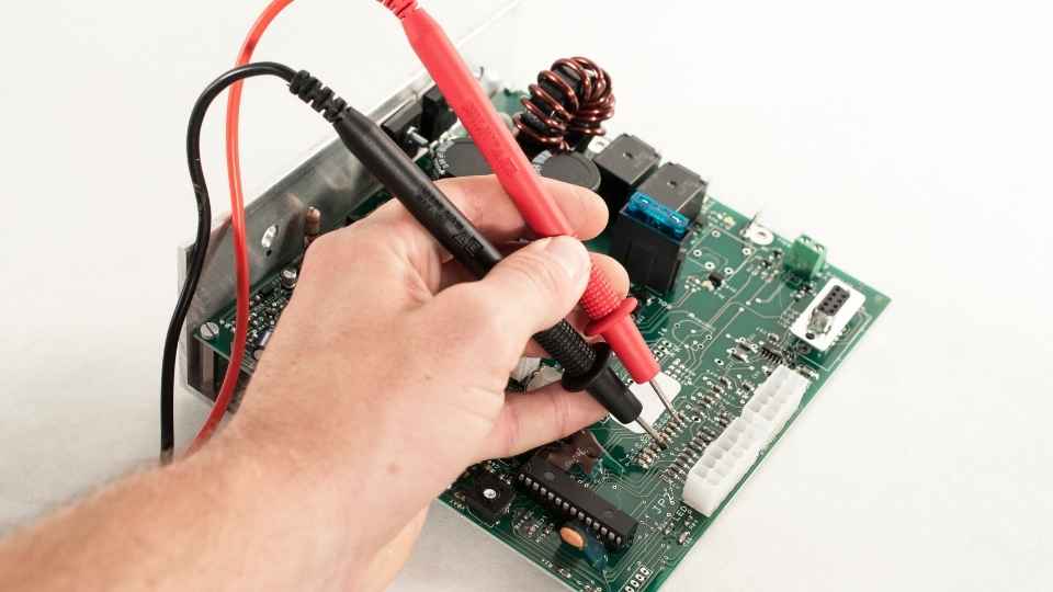
When it comes to accurately measuring current flow within a circuit, technicians and engineers rely on precise instrumentation and techniques. Current flow measurement is crucial in various applications, such as circuit analysis, power management, and system troubleshooting.
To measure current, professionals typically use ammeters or multimeters capable of reading current values. These instruments are connected in series with the component or circuit under investigation to obtain an accurate measurement.
To ensure reliable measurements, it is essential to select the appropriate range on the instrument that can accommodate the expected current level. Additionally, technicians should take into account factors like temperature coefficients and internal resistance when interpreting readings.
Furthermore, different techniques can be employed for measuring alternating currents (AC) versus direct currents (DC). AC measurements often involve using RMS (root mean square) values while DC measurements typically rely on direct voltage drop across a known resistor.
Practical Applications of Electronic Calculations
One essential application of electronic calculations is in determining the appropriate resistor values to achieve desired voltage levels in a circuit. This process involves using Ohm's Law and various formulas to calculate the resistance needed for specific voltage requirements.

The practical applications of electronic calculations are vast and varied, catering to the needs of individuals seeking freedom in their projects. Some notable applications include:
Power supply design:
Calculating resistors for voltage regulation
Determining power dissipation and heat management
Audio systems:
Designing amplifiers with desired gain levels
Calculating impedance matching for speakers
Frequently Asked Questions
How Can I Calculate the Power Dissipation in a Resistor?
To calculate the power dissipation in a resistor, use Ohm's Law (P = I2 * R) or Joule's Law (P = V2 / R), where P is power, I is current, V is voltage, and R is resistance.
The formula for calculating the time constant of an RC circuit is given by the product of resistance (R) and capacitance (C). It is an important parameter in determining the behavior of such circuits.
How Do I Determine the Voltage Across Each Resistor in a Voltage Divider Circuit?
To determine the voltage across each resistor in a voltage divider circuit, you can use Ohm's Law and the concept of proportionality. By calculating the resistance values and applying the voltage division formula, you can find the desired voltages accurately.
Can You Explain Kirchhoff's Current Law and How It Is Used in Current Flow Analysis?
Kirchhoff's current law is a fundamental principle in circuit analysis. It states that the total current entering a node is equal to the total current leaving that node. This law is used to analyze and calculate currents in complex circuits.
What Are Some Common Real-Life Applications Where Electronic Calculations Are Used?
Common real-life applications where electronic calculations are used include circuit design and analysis, power distribution systems, telecommunications networks, electrical equipment testing and troubleshooting, signal processing, control systems, and data analysis in scientific research and engineering fields.
 Basic Electronics ConceptsEssential ToolsCircuit Design BasicsMicrocontrollersDIY Electronics ProjectsRoboticsPrivacy PolicyTerms And Conditions
