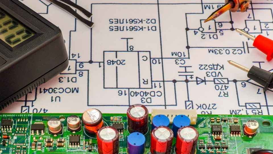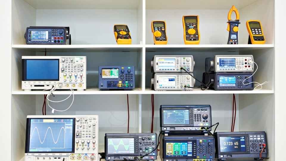
In the fast-paced world of high-speed circuit design, ensuring signal integrity becomes paramount. Like a well-oiled machine, these circuits must flawlessly transmit data at lightning speed, without any glitches or disruptions. A misstep in this delicate dance could lead to catastrophic consequences for electronic systems.
Therefore, mastering the art of signal integrity is crucial for engineers and designers alike. In this article, we will delve into the intricacies of high-speed circuit design and explore techniques that guarantee signal integrity in even the most demanding scenarios.
Key Takeaways
- Factors such as attenuation, dispersion, reflections, and crosstalk can affect signal propagation at high speeds in high-speed circuit design.
- Impedance matching, proper spacing and shielding techniques, and accounting for losses are essential for maintaining reliable communication in high-speed electronic systems.
- Understanding and mastering termination techniques, such as series termination, parallel termination, and differential termination, is crucial for minimizing signal reflections and optimizing transmission line performance.
- Considering signal frequency, transmission line characteristics, termination component properties, and reflection coefficient helps ensure robust signal integrity in high-speed circuit design.
Understanding Signal Propagation
To ensure robust signal integrity at high speeds, it is imperative to have a comprehensive understanding of signal propagation and its various factors.
Signal propagation refers to the transmission of electrical signals through different mediums, such as wires or PCB traces.
At high speeds, several factors can affect signal propagation, including attenuation, dispersion, reflection, and crosstalk.
Attenuation refers to the loss of signal strength as it travels through a medium.
Dispersion occurs when different frequencies within a signal propagate at different velocities, causing distortion.

Reflections can occur when a signal encounters impedance mismatches or sharp changes in the transmission line geometry.
Crosstalk happens when signals interfere with each other due to coupling between adjacent traces or components.
Understanding these factors allows designers to implement appropriate measures like controlled impedance routing, termination techniques, and shielding strategies to minimize their impact on signal integrity and maintain reliable communication in high-speed circuit designs.
Essentials of Transmission Lines
The understanding of transmission line fundamentals is crucial for maintaining reliable communication in high-speed electronic systems.
To ensure signal integrity at high speeds, it is essential to consider the following:
Impedance Matching: Proper impedance matching between the source and load impedances ensures efficient power transfer and minimizes signal reflections.
Terminations: Adding termination resistors at the ends of transmission lines prevents signal reflections and reduces noise.

Crosstalk: Implementing proper spacing and shielding techniques helps minimize crosstalk between adjacent transmission lines, reducing interference.
Losses: Accounting for losses due to resistance, dielectric materials, and skin effect helps optimize signal quality by minimizing attenuation.
Mastering Termination Techniques
Implementing proper termination techniques is essential for minimizing signal reflections and optimizing the performance of transmission lines in electronic systems. In high-speed circuit design, where signal integrity becomes increasingly critical, mastering these techniques is paramount.
Termination refers to the way a transmission line is terminated at its end to prevent unwanted signal reflections that can degrade the quality of the transmitted signals. The goal is to match the impedance of the transmission line with that of its load or source so that there are no reflected signals.
Common termination techniques include series termination, parallel termination, and differential termination. Each technique has its advantages and disadvantages depending on factors such as data rate, distance, and noise susceptibility.
Bandwidth Considerations
Bandwidth considerations play a crucial role in selecting the appropriate termination technique for optimizing signal performance and minimizing unwanted reflections in transmission lines. When designing high-speed circuits, it is essential to take into account the bandwidth requirements of the signals being transmitted. Here are four key factors to consider:
Signal frequency: The higher the frequency, the wider the bandwidth required for accurate signal transmission. It is important to choose a termination technique that can handle the desired frequency range.

Transmission line characteristics: Different transmission lines have varying impedance characteristics, which impact signal integrity. Understanding these characteristics helps in determining suitable termination techniques.
Termination component properties: Termination components such as resistors or capacitors have their own bandwidth limitations. Selecting components with appropriate bandwidth ratings ensures optimal signal integrity.
Reflection coefficient: Unwanted reflections occur when there is a mismatch between the impedance of the transmission line and its termination. Minimizing reflection coefficients within acceptable limits enhances signal quality.
Considering these factors enables engineers to make informed decisions regarding termination techniques that will ensure robust signal integrity at high speeds while maintaining freedom from unwanted reflections in transmission lines.
Exploring Differential Signaling
Exploring the advantages of differential signaling allows engineers to optimize signal transmission and minimize interference in high-frequency applications.
Differential signaling is a technique that involves using two complementary signals, where one is the inverse of the other, to represent data. This method provides several key benefits for high-speed circuit design.
Firstly, by transmitting data differentially, engineers can achieve improved noise immunity. Any common-mode noise that is present in both signals will be cancelled out at the receiver, resulting in a more reliable and accurate transmission.

Secondly, differential signaling enables better impedance control. By matching the characteristic impedance of the transmission line to the differential impedance of the driver and receiver circuits, signal reflections can be minimized, thereby reducing signal degradation.
Additionally, this technique offers increased data rate capabilities. The use of differential pairs allows for higher bandwidths and faster switching speeds since it effectively doubles the effective voltage swing between states.
Frequently Asked Questions
What Are Some Common Challenges Faced When Designing High-Speed Circuits?
When designing high-speed circuits, engineers often encounter challenges related to signal integrity. These can include issues such as impedance matching, crosstalk, and electromagnetic interference, all of which must be carefully addressed to ensure reliable operation at high speeds.
How Do Signal Propagation and Signal Integrity Relate to Each Other in High-Speed Circuit Design?
Signal propagation and signal integrity are crucial factors in high-speed circuit design. The speed at which signals travel through a circuit affects their integrity, and ensuring signal integrity is essential for reliable data transmission and system performance.
What Are Some Key Factors to Consider When Selecting Transmission Lines for High-Speed Circuitry?
When selecting transmission lines for high-speed circuitry, key factors to consider include impedance matching, signal attenuation, crosstalk, and electromagnetic interference. These factors are crucial in ensuring signal integrity and preventing data loss or distortion.
How Can Termination Techniques Be Optimized to Ensure Signal Integrity in High-Speed Circuit Design?
Optimizing termination techniques is crucial for ensuring signal integrity in high-speed circuit design. By carefully selecting the appropriate termination resistors and matching impedance levels, potential reflections and signal distortions can be minimized, resulting in improved overall performance.
What Are the Advantages and Disadvantages of Differential Signaling in High-Speed Circuitry?
Differential signaling offers several advantages in high-speed circuitry, such as improved noise immunity and higher data rates. However, it also requires additional hardware complexity and increased power consumption compared to single-ended signaling.

 Basic Electronics ConceptsEssential ToolsCircuit Design BasicsMicrocontrollersDIY Electronics ProjectsRoboticsPrivacy PolicyTerms And Conditions
