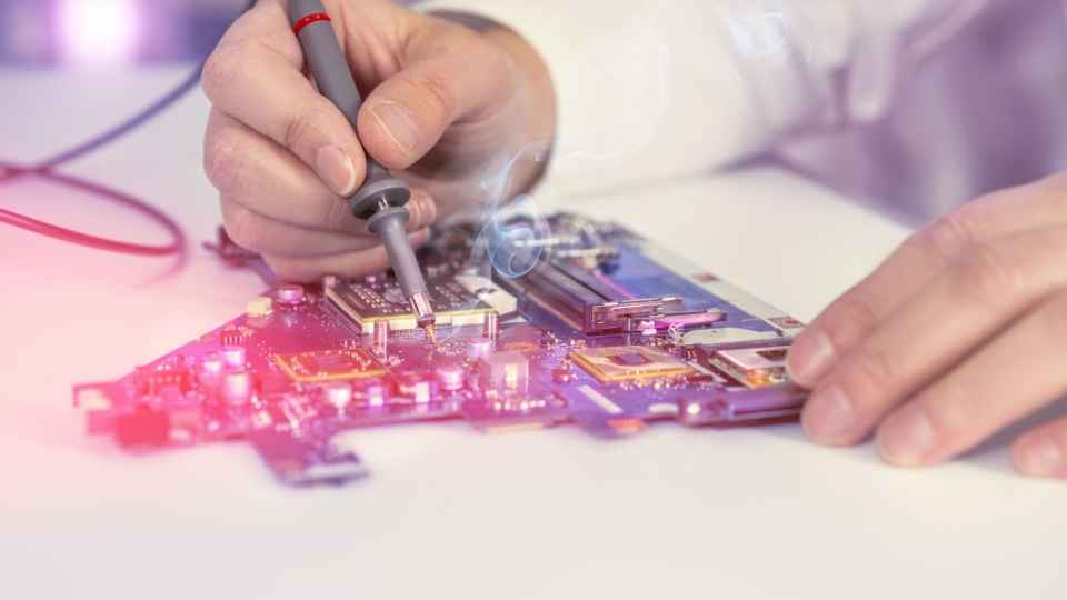
In the world of electronics, circuit testing and verification are crucial steps in ensuring the functionality and reliability of electronic devices.
To effectively perform these tasks, one must have a comprehensive understanding of oscilloscopes and analyzers.
Oscilloscopes provide visual representations of electrical signals, while analyzers offer in-depth analysis and measurement capabilities.
This article explores the fundamentals of using oscilloscopes and analyzers for circuit testing and verification purposes, providing valuable insights into advanced techniques, applications, and best practices for efficient utilization.
Key Takeaways
- Circuit testing is crucial for ensuring the functionality, reliability, and safety of electrical systems.
- Oscilloscopes and analyzers are essential tools in circuit testing and verification.
- Proper grounding, adjusting timebase settings, triggering, and measurement functions are effective techniques for using oscilloscopes and analyzers in circuit testing.
- Analyzers have advanced applications such as spectral analysis, eye diagram analysis, and advanced triggering capabilities that enhance circuit verification.
The Importance of Circuit Testing and Verification
Circuit testing and verification play a crucial role in ensuring the functionality, reliability, and safety of electrical systems. It is imperative to test circuits thoroughly before deployment to identify any potential issues that can affect performance or compromise safety.
Through systematic testing, engineers can validate the accuracy and effectiveness of circuit designs, ensuring that they meet specific requirements. Verification involves confirming that the circuit operates within expected parameters and conforms to industry standards. This process helps identify faults, errors, or inconsistencies that may arise during operation.
By using advanced tools such as oscilloscopes and analyzers, engineers can analyze various electrical signals and waveforms to diagnose problems accurately.

Effective circuit testing and verification are essential for achieving optimal performance and reliability in electrical systems while maintaining the freedom from potential hazards for users.
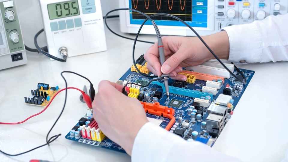
Understanding Oscilloscopes: Basics and Application
Oscilloscopes are indispensable tools for engineers and technicians to visualize and analyze electrical waveforms, providing valuable insights into the behavior and performance of electronic systems. They allow for precise measurement and analysis of voltage, current, frequency, and phase relationships within a circuit.
Oscilloscopes can capture and display both repetitive and single-shot waveforms, enabling users to investigate transient events or complex signals. These devices offer various triggering options to isolate specific parts of a waveform for detailed examination.
Additionally, advanced oscilloscopes include features such as automatic measurements, math functions, spectrum analysis, and serial protocol decoding capabilities that enhance their usefulness in troubleshooting circuits. With their ability to accurately display electrical signals in real-time, oscilloscopes empower engineers with the freedom to identify issues quickly and efficiently optimize circuit designs or diagnose faults within electronic systems.
Analyzers: An Overview of Different Types and Their Functions
Analyzers play a crucial role in various industries and disciplines. They aid in the analysis and measurement of different types of signals, data, and systems. These devices come in a variety of types, each designed to perform specific functions and cater to specific needs.
Understanding the different types and their respective functions is essential for effectively utilizing analyzers in various applications.
Types of Analyzers
The various types of analyzers available in the market offer a wide range of functionalities and features for comprehensive circuit testing and verification. One type is the logic analyzer, which is used to analyze digital signals and capture data from multiple channels simultaneously. It provides powerful triggering capabilities and can display waveforms, state diagrams, timing diagrams, and protocol decodes.

Another type is the spectrum analyzer, which is used to measure frequency domain characteristics of signals. It can display amplitude versus frequency plots and identify signal frequencies, amplitudes, harmonics, and distortions.
Additionally, there are network analyzers that measure electrical networks' response to electrical stimuli at different frequencies. They provide accurate measurements of impedance, reflection coefficient, insertion loss, return loss, and phase shift across a wide frequency range.
These different types of analyzers have specific functions and uses that make them essential tools in circuit testing and verification processes.
Analyzer Functions and Uses
One of the key functions of logic analyzers is their ability to capture data from multiple channels simultaneously, allowing for comprehensive analysis of digital signals. This feature enables engineers to analyze complex digital systems with ease and precision.
Logic analyzers can capture and display waveforms, timing diagrams, state machine traces, and protocol decoding in real-time. With their high-speed sampling rates and deep memory capabilities, they can effectively detect and troubleshoot issues such as glitches, timing violations, and signal integrity problems.
Additionally, logic analyzers offer advanced triggering options that enable engineers to pinpoint specific events or conditions for further analysis. They also provide powerful software tools for data manipulation, filtering, and visualization.
Overall, logic analyzers are essential tools for circuit testing and verification as they allow engineers the freedom to thoroughly analyze digital signals in order to ensure optimal performance and reliability.

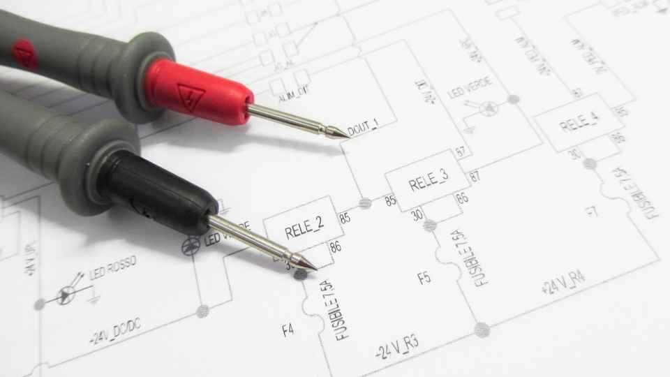
Effective Techniques for Using Oscilloscopes in Circuit Testing
To maximize the efficiency of circuit testing, it is essential to employ effective techniques when utilizing oscilloscopes. These powerful tools allow engineers to analyze waveforms and measure various electrical parameters.
Here are some techniques that can help in using oscilloscopes effectively:
Proper grounding and shielding: Ensuring a solid ground connection and using proper shielding techniques can minimize noise interference in measurements.
Adjusting timebase settings: Setting the timebase appropriately helps in capturing the desired waveform details without distortion.
Using trigger settings: Triggering allows for stable waveform capture by synchronizing with specific events or signal characteristics.
Utilizing measurement functions: Oscilloscopes offer a range of built-in measurement functions like voltage, frequency, rise/fall time, etc., which aid in analyzing signal characteristics.
Advanced Applications of Analyzers in Circuit Verification
By exploring the advanced capabilities of analyzers, engineers can push the boundaries of circuit verification and gain deeper insights into signal analysis and troubleshooting. Analyzers are powerful tools that enable engineers to measure and analyze various parameters of electronic signals, such as amplitude, frequency, phase, and distortion. These devices provide a detailed view of signal behavior in both time and frequency domains, allowing engineers to identify potential issues or anomalies within a circuit.
One advanced application of analyzers is the ability to perform spectral analysis. By examining the frequency content of a signal, engineers can determine if any unwanted noise or interference is present. This information is crucial for designing circuits with high signal-to-noise ratios.
Another valuable feature offered by some analyzers is the capability to perform eye diagram analysis. This technique allows engineers to visualize how a digital signal evolves over time and assess its quality by analyzing parameters like rise time, fall time, jitter, and noise margin.
Furthermore, modern analyzers often come equipped with advanced triggering capabilities that allow users to capture specific events or patterns within a complex waveform accurately. This enables engineers to isolate incidents for further analysis without being overwhelmed by irrelevant data.
Overall, by leveraging these advanced capabilities of analyzers in circuit verification processes, engineers can gain deeper insights into signal behavior and troubleshoot more effectively. These tools empower them with the freedom to explore complex waveforms thoroughly and ensure reliable performance in their designs.
Tips and Best Practices for Efficient Use of Oscilloscopes and Analyzers
Efficient use of oscilloscopes and analyzers is essential for accurate waveform analysis and data interpretation. To ensure optimal performance, it is important to follow best practices such as:
- Calibrating the instruments regularly
- Using appropriate probe settings
- Selecting the appropriate measurement parameters
Additionally, understanding the functionality of various features and utilizing advanced analysis tools can further enhance efficiency and accuracy in measuring and analyzing electronic signals.
When analyzing waveforms on an oscilloscope, it is important to carefully observe the voltage levels and time intervals to accurately diagnose any circuit issues.
Here are some key points to keep in mind while analyzing waveforms:
Voltage Levels: Pay close attention to the amplitude of the waveform, as it provides information about the signal strength or power level.
Time Intervals: Analyze the time duration between different points of interest on the waveform, such as rise and fall times, pulse widths, and period.
Signal Distortion: Look for any abnormalities or distortions in the waveform shape that could indicate issues like noise, harmonics, or ringing.
Triggering: Set up appropriate trigger settings to capture specific events or patterns in the waveform.
By carefully observing these aspects of a waveform, you can gain valuable insights into circuit behavior and identify potential problems.
Now let's move on to discussing how to interpret analyzer data effectively.
Analyzer Data Interpretation
Now that we have explored the realm of oscilloscope waveform analysis, let us delve into the next crucial aspect of circuit testing and verification: analyzer data interpretation.
Analyzers provide invaluable insights into the behavior and performance of electrical systems by analyzing various parameters such as voltage, current, frequency, and phase.
The process of interpreting analyzer data requires a meticulous approach that involves understanding complex waveforms, identifying patterns or anomalies, and drawing meaningful conclusions based on objective analysis.
This task demands a high level of technical proficiency and analytical skills to extract accurate information from the vast array of data generated by analyzers.
Frequently Asked Questions
What Are the Common Challenges Faced When Using Oscilloscopes and Analyzers for Circuit Testing and Verification?
Common challenges in using oscilloscopes and analyzers for circuit testing and verification include understanding complex functionalities, interpreting waveform data accurately, troubleshooting signal integrity issues, ensuring proper probe calibration, and managing noise interference.
How Do Oscilloscopes and Analyzers Contribute to Improving the Overall Quality and Reliability of Electronic Circuits?
Oscilloscopes and analyzers play a crucial role in enhancing the quality and reliability of electronic circuits. By providing accurate measurements and analysis, they enable engineers to identify and address issues, ensuring optimal circuit performance.
Are There Any Specific Safety Precautions That Need to Be Taken When Using Oscilloscopes and Analyzers in Circuit Testing?
When using oscilloscopes and analyzers for circuit testing, it is crucial to prioritize safety precautions. This includes ensuring proper grounding, using appropriate personal protective equipment, and following manufacturer guidelines to avoid electrical hazards and damage to the equipment.
Can You Provide Some Examples of Real-Life Scenarios Where Oscilloscopes and Analyzers Have Been Instrumental in Troubleshooting Circuit Issues?
Oscilloscopes and analyzers have proven to be crucial tools in troubleshooting circuit issues. Real-life scenarios include diagnosing signal distortions, identifying faulty components, and analyzing data transmission problems, improving overall circuit performance and reliability.
Are There Any Limitations or Drawbacks to Using Oscilloscopes and Analyzers in Circuit Testing That Engineers Should Be Aware Of?
There are limitations and drawbacks to using oscilloscopes and analyzers in circuit testing. Engineers should be aware of potential inaccuracies, limited bandwidth or sampling rate, and the need for proper calibration and setup to ensure reliable results.
 Basic Electronics ConceptsEssential ToolsCircuit Design BasicsMicrocontrollersDIY Electronics ProjectsRoboticsPrivacy PolicyTerms And Conditions