
Are you ready to embark on an exciting journey into the world of circuit design? Whether you're a seasoned engineer or a curious novice, this article is your ultimate guide to mastering the fundamental principles of circuit design.
Get ready to unleash your creativity as we explore the intricate workings of basic components and tools. From deciphering complex circuit diagrams to troubleshooting common issues, this comprehensive resource will equip you with the knowledge and skills needed to bring your ideas to life.
Get prepared for a transformative learning experience like no other.
Key Takeaways
- Resistors, capacitors, diodes, and transistors are fundamental building blocks in circuit design.
- Circuit diagrams provide a systematic approach to understanding, troubleshooting, and identifying potential issues in circuits.
- Circuit symbols convey important information about the function and properties of electronic components.
- Multimeters, breadboards, and PCB design software are essential tools for circuit design.
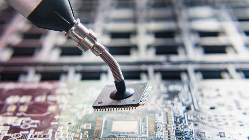
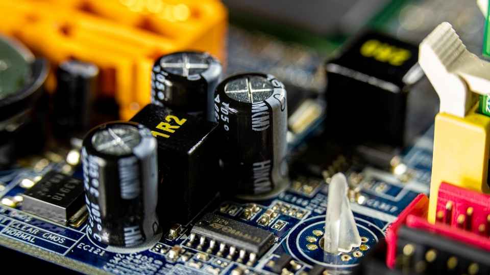
Understanding the basics of components and tools is essential for getting started with circuit design. In order to create electronic circuits, it is important to have a thorough understanding of the various components and tools used in the process. Components such as resistors, capacitors, diodes, and transistors are fundamental building blocks that allow for the manipulation of electrical signals. These components come in different values and sizes, which determine their specific functions within a circuit.
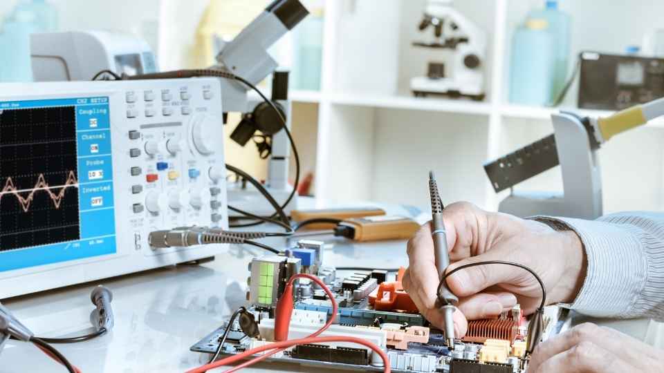
Additionally, there are various tools that aid in circuit design. A breadboard is commonly used to prototype circuits without soldering, allowing for easy experimentation and modification. Multimeters are essential for measuring voltage, current, and resistance values in a circuit. Oscilloscopes help visualize waveforms and analyze signal behavior.
Reading Circuit Diagrams: A Step-by-Step Guide
Reading Circuit Diagrams: A Step-by-Step Guide provides a comprehensive overview of the essential skills required to interpret and understand circuit diagrams.
This guide offers a systematic approach, breaking down complex diagrams into manageable steps.
Understanding Circuit Symbols
Familiarity with circuit symbols is crucial for engineers and designers as it allows for effective communication and interpretation of schematic diagrams. Circuit symbols are graphical representations of electronic components, such as resistors, capacitors, transistors, and integrated circuits. These symbols provide a standardized way to represent these components in circuit diagrams, making it easier for engineers to understand and design electrical circuits.
Each symbol has a specific meaning that conveys important information about the component's function, properties, and connections within the circuit. For example, a resistor symbol represents a passive component that resists the flow of electric current. By recognizing this symbol, engineers can quickly identify the presence of a resistor in a circuit diagram and analyze its impact on overall circuit behavior.
Furthermore, familiarity with circuit symbols allows engineers to communicate their ideas effectively with colleagues or clients. It enables freedom in expressing complex electrical concepts concisely through visual representation.
Overall, understanding circuit symbols is an essential skill for anyone involved in electronics design or engineering projects as it promotes efficient collaboration and accurate interpretation of schematic diagrams.
Interpreting Connection Between Components?
The accurate interpretation of the connection between components in a schematic diagram is crucial for engineers and designers to ensure proper functionality and performance of the electrical circuit.
A schematic diagram represents an electrical circuit using symbols that depict various components such as resistors, capacitors, transistors, and integrated circuits. Each component is connected by lines that indicate how they are electrically linked.
These connections can be represented in different ways depending on the type of circuit being designed. For example, series connections show components connected one after another along a single path, while parallel connections indicate multiple paths where current can flow simultaneously.

When it comes to circuit design, having the right tools is essential for accurate and efficient work.
Three key tools that every circuit designer should have in their arsenal are:
- A multimeter for component testing
- A breadboard for prototyping
- PCB design software
These tools enable designers to:
- Test and measure components
- Quickly prototype circuits
- Create professional-grade printed circuit board designs.
Multimeter for Component Testing
Using a multimeter is essential for accurately testing and measuring the performance of electronic components in circuit design. A multimeter is a versatile tool that combines multiple measurement functions into one device, allowing engineers to measure voltage, current, resistance, and continuity. It consists of a digital or analog display, probes for connecting to the circuit under test, and various knobs or buttons for selecting different measurement modes.
When testing electronic components in circuit design, a multimeter can provide valuable information about their behavior and characteristics. For example, it can help determine if a resistor has the correct resistance value or if a diode is functioning properly. By measuring voltage across different points in a circuit, engineers can identify potential issues such as shorts or open circuits.
In addition to component testing, a multimeter is also useful for troubleshooting faulty circuits by identifying faulty connections or defective components. This allows engineers to quickly diagnose and fix problems during the development phase.
Overall, using a multimeter in circuit design provides engineers with the freedom to accurately test and measure electronic components while ensuring optimal performance and functionality of the final product.

Breadboard for Prototyping
Breadboards are essential tools for engineers to prototype and test electronic circuits before they are implemented on a printed circuit board (PCB). They provide a convenient platform for creating temporary connections between components, allowing for rapid experimentation and iteration.
Here are four reasons why breadboards are favored by engineers:
Flexibility: Breadboards offer the freedom to easily modify or rearrange circuits without the need for soldering or permanent connections.
Time-saving: With breadboards, engineers can quickly test different component configurations, saving valuable time during the design process.
Cost-effective: Breadboards eliminate the need for costly PCB fabrication during initial prototyping stages.
Learning tool: Using breadboards allows engineers to gain hands-on experience with circuit design principles and component functionality.
Overall, breadboards empower engineers with the freedom to explore and innovate while designing electronic circuits.

PCB Design Software
PCB design software plays a crucial role in streamlining the process of transforming electronic circuit designs into functional printed circuit boards. This software provides engineers with a platform to design, test, and optimize their circuits before sending them for fabrication. With a wide range of features and tools, PCB design software allows users to create schematic diagrams, place components on the board, define routing paths, and generate manufacturing files.
One of the key advantages of using PCB design software is the ability to visualize the circuit layout in a digital format. This allows for easy identification of errors or potential issues before moving forward with prototyping. Additionally, the software offers advanced functionalities such as auto-routing capabilities, signal integrity analysis, and 3D visualization.
Transitioning from PCB design software to prototyping involves taking the digital representation of the circuit and turning it into a physical prototype. Let's now explore some basics on how to bring your ideas to reality by building prototypes.
Prototyping Basics: From Idea to Reality
To transform an idea into a tangible product, it is crucial to understand the prototyping basics and the necessary steps to bring that concept from imagination to reality. Prototyping allows engineers and designers to test their ideas, iterate on designs, and identify any potential issues before moving forward with full-scale production.
Here are four key steps in the prototyping process:
Define your objectives: Clearly outline what you want to achieve with your prototype and establish specific goals.
Choose the right materials: Select materials that closely resemble the final product's properties to ensure accurate testing.
Build a functional prototype: Use tools like 3D printers or circuit simulation software to create a working model of your design.
Test and refine: Conduct thorough testing and collect feedback to identify areas for improvement, allowing you to iterate on your design until it meets all requirements.
Now that we have covered the basics of prototyping, let's move on to the next step: layout design. This crucial phase involves optimizing your circuit's performance by carefully arranging components and traces on a PCB (printed circuit board).
Layout design plays a significant role in ensuring signal integrity, minimizing noise, and maximizing efficiency. To achieve these goals, it is essential to consider factors such as component placement, trace routing, power distribution, and grounding techniques.
Proper component placement involves determining the optimal location for each element to minimize trace lengths and reduce parasitic effects. Trace routing should be optimized for impedance matching and signal integrity while considering high-speed signals or sensitive analog circuits.
Power distribution should be designed to minimize voltage drops and ensure stable operation. Grounding techniques help prevent ground loops and maintain reference potential.
Troubleshooting Common Circuit Design Issues
Effective troubleshooting techniques are essential for identifying and resolving common issues that may arise during the development of electronic circuits. Here are four key techniques to help you troubleshoot circuit design issues:

Analyze the schematics: Carefully review the circuit diagrams to ensure all connections are correct and components are properly placed.
Check power supply: Verify that the power supply is delivering stable voltage levels within the specified range, as fluctuations can cause circuit malfunctions.
Test components: Use multimeters or oscilloscopes to measure component values and waveforms, ensuring they meet expected specifications.
Divide and conquer: Isolate sections of your circuit by disconnecting specific components or modules to identify which part is causing the problem.
By applying these troubleshooting techniques, you can effectively diagnose and resolve issues in your electronic circuits.
With a solid foundation in troubleshooting, you will be better equipped to tackle more advanced techniques and next steps in circuit design.
Advanced Techniques and Next Steps in Circuit Design
By expanding your knowledge of advanced techniques and exploring the next steps in electronic circuit development, you can enhance your skills as a circuit designer. One such advanced technique is the use of programmable logic devices (PLDs) and field-programmable gate arrays (FPGAs). These devices offer greater flexibility and functionality compared to traditional fixed-function integrated circuits. With PLDs and FPGAs, you can design complex digital systems by programming their logic functions using hardware description languages (HDLs) like VHDL or Verilog.
Another important aspect of advancing in circuit design is understanding high-frequency signal integrity issues. As circuits operate at higher frequencies, transmission line effects become significant, resulting in impedance mismatches and signal reflections. To mitigate these issues, designers must consider controlled impedance routing techniques, termination schemes, and proper grounding practices.
Additionally, exploring analog circuit design principles such as feedback theory and frequency response analysis will enable you to create more robust and reliable circuits. Furthermore, gaining proficiency in simulation tools like SPICE will allow for accurate prediction of circuit behavior before physical implementation.
Frequently Asked Questions
What Are the Different Types of Resistors and When Should I Use Each Type?
There are various types of resistors available, including carbon composition, metal film, and wire wound resistors. The choice depends on factors such as power rating, tolerance, and temperature coefficient required for the specific circuit design.
How Do I Choose the Right Capacitor for My Circuit Design?
Choosing the right capacitor for circuit design requires considering factors such as capacitance value, voltage rating, and tolerance. Understanding the specific requirements of your circuit and consulting datasheets can help ensure optimal performance and reliability.
Can I Use a Breadboard for Prototyping Complex Circuits?
Yes, a breadboard can be used for prototyping complex circuits. It allows for easy and quick experimentation with various components and connections without the need for soldering. However, it may have limitations in terms of high-frequency applications or longer-term reliability.
What Are the Common Mistakes to Avoid When Designing a Circuit Layout?
Common mistakes to avoid when designing a circuit layout include inadequate spacing between components, improper grounding techniques, lack of proper heat dissipation mechanisms, and failure to consider electromagnetic interference (EMI) issues.
Testing and debugging a circuit for performance issues involves using various tools such as multimeters, oscilloscopes, and logic analyzers to measure voltage, current, and signal integrity. Troubleshooting techniques include checking connections, analyzing waveforms, and identifying faulty components.

 Basic Electronics ConceptsEssential ToolsCircuit Design BasicsMicrocontrollersDIY Electronics ProjectsRoboticsPrivacy PolicyTerms And Conditions